Light Sculptures
A Small Network of LEDs
These projects all use a single RGB LED connected to a PIC microprocessor. A number of these are connected together daisy-chain style into a small network. The network is then run by another PIC, or by the first PIC in the daisy chain. To simplify programming, all the PICs are programmed with the same code, except for the first PIC in the chain. Once a second, the first PIC in the chain sends a special packet to the next PIC in the chain. This packet tells the PIC to set its address to the contents of the packet, then increment the address by one, and forward the packet to the next PIC in the chain. This permits all PICs to have a unique address without having to program each PIC with a unique address. If no packet is received by a PIC, the PIC resets itself and flashes its LEDs. This makes searching for broken connections in the chain very straightforward. The daisy chain also simplifies connecting units, as there are only three wires (power, ground and input) going into each module and three wires ( power, ground, and output) coming out of each module. This allows large sculptures to be built without a lot of wires running everywhere. Some examples:
The Angel

The Angel uses textured PVC pipe to both block and reflect the the light from the LEDs give a dramatic contrast to each layer of the sculpture. The color propagates from the center tube outwards to the other layes for a pleasing ripple effect.
The Lamp
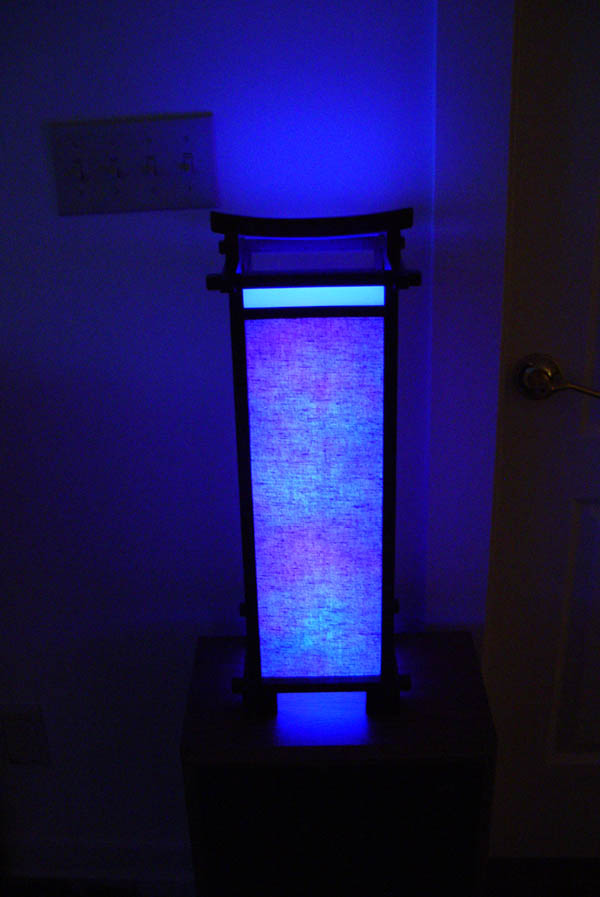
I found a nice lamp at World Market that had a simple diffuser of thin plastic and cloth. I placed a daisy chain of a dozen or so lights into the lamp. The diffuser gives a nice effect, almost like an abstract watercolor painting.
The Clock

The clock consists of a daisy chain of 60 RGB LEDs mounted in a circle. A master PIC connected to a wireless link drives the daisy chain. The other end of the wireless link is connected to a Rabbit Semiconductor (basically a glorified Z80) ethernet module in the basement. The rabbit accesses NTP servers over the Internet and sends the time over the wireless link to the clock on the wall in the kitchen. The master PIC then uses the time to set the LEDs to the proper time. Red is used as the hour hand, green is the minute hand, and blue is the second hand. The rest of the LEDs are set to a particular theme depending on the season; red+green for Winter, cyan+green for Spring, yellow+green for Summer, and magenta+orange for Fall. From midnight to 5AM the display uses gray+dark gray as a reminder that it is late and I should get to bed.
The Nightlight

I built these for the kids as a Christmas present. Each nightlight has a daisy chain of 12 RGB LEDs and is designed to slowly change color. They are pretty bright for nightlights. The housing is made of glass 'ice cubes' hot-glued together, with the middle layer hollow. Two plastic diffusers (front and back) and the LEDs are mounted in this hollow area.
The Rocket
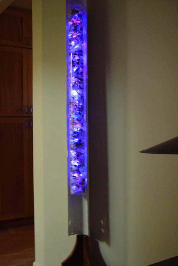
This is a four-foot-high acrylic tube four inches in diameter. The central part has a set of 32 RGB LEDs mounted so that 16 are facing front and 16 are facing back. Packed around this is tumbled glass of various shapes and colors. The rear reflector is textured PVC pipe. The software selects a complementary color for the rear-facing LEDs based on the front-facing color, although occasionally (i.e. randomly) all the LEDs are the same color. A wooden base is constructed so that the sculpture leans agains the wall.
Software
The pictures above don't really capture the changing colors. Initially I had the colors changing randomly, all the time, but this was just too chaotic. It reminded me of a TV set tuned to an unused channel - just white noise. What seems to be the most pleasing (to me, anyway) is to (randomly) pick a target color and slowly change all the nodes to that color (in a random way, of course). Then the color is held briefly and another color is selected and the transition begins again. The color and node selection is done by the first PIC in the chain. The PIC sends a packet containing the node number and RGB levels for that node. The RGB levels are used to set the PWM duty cycle for each LED. The PWM duty cycle generator is a software loop running at about 10kHz and varies the intensity of each LED from 0 (off) to 100 (full on).
Hardware
Each node consists of a PIC micro (either a PIC 16F88 or a PIC 16F688) that controls the RGB LED and gets input via its serial port RX line at 38400 baud. Packets are forwarded out the serial port TX line to the next PIC in the chain. A packet with a node address that matches the address of the PIC is not forwarded.
If you've got questions regarding this project, email me at: p r o j e c t _ q u e s t i o n s at k y s o t e c h . c o m
tony ozrelic, mar. 2007