skatanova, a self-balancing skateboard
skatanova links
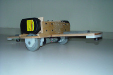
After building rotanova, I decided to revisit the skateboard concept and see just how cheap I could make it while keeping it functional. Observing rotanova in action, I found that reversing direction did not happen all that often, and so I decided to make a motor controller using relays to reverse the drive motors instead of a more expensive set of burly MOSFETs. This reduced each motor controller to one moderately sized DPDT relay and one burly IRFP2907 MOSFET, plus a relay driver IC and a PIC 18F2620 microcontroller.
Motors
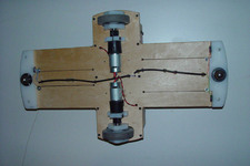
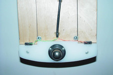
For motors, Harbor Freight had 14.4V cordless drills on sale for $US9.99 each, so I bought two of those.The wheels are 4 inch Colson wheels with a keyed hub that mounts directly to the drill motors. The wheels and hubs come from CNCbotparts.com. Note the cutouts on the base; these define areas that are used as foot-operated switches. The left switch is used for power, and the right two switches are used for steering.
Batteries
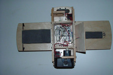
Since the drills came with their own rechargeable battery and charger, I decided to use those in the design as well. I used 1/2 inch baltic birch plywood for the base and enclosure, and 1/2 inch HDPE (high-density polyethylene) as motor mounts, bearing blocks, and skid plates. Even though HDPE is slippery, I found that max speed runs slowed dramatically, so I added a ball caster to the front and back to minimize drag.
Controls
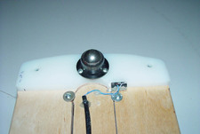
To control the deck, one foot applies power and the other steering. Basically these are foot switches which use cutouts on the deck as a sort of springy lever. When the lever is depressed by the rider's foot, the edge of the plywood moves down and actuates a microswitch bolted to the skid plate on the bottom of the board. The screws and washers limit the travel of the lever so the user doesn't crush the switch. No doubt something more exotic (and reliable) could be engineered, but this serves well enough for now.
Electronics
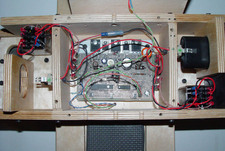
The control electronics are fairly simple, just a couple of regulators to step the 28.8 volts from the drill batteries to 12V, then to 5V for the controller logic. A PIC digitizes the analog inputs from the gyro and accelerometers and outputs a PWM signal for each motor. The signals go from the PIC to the SN754410 relay driver, which drives the reversing relays and the motor MOSFETs.
Gyro/Accelerometer
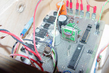
Here's the gyro/accelerometer bracket. The accelerometer is mounted on the far side of the bracket at a 45 degree angle, same as in rotanova. The connectors at the bottom edge of the board are for connecting a serial port, programming the PIC, and a remote control adapted from a wireless PS2 game controller. Please excuse the mess; I forgot to blow the sawdust out before taking the picture.
Observations and Acknowledgements
This contraption went through many changes before I gave up and started working on rotanova. After rotanova was working I revisited the idea and eventually got to what you see here.
One of the ideas was to have the rider perch on a deck above the controller, banking the deck to steer and tilting it to move forward and back. This turned out to be hard to implement as well as downright scary to operate, as you are about 10 inches off the floor on a wildly bucking platform.
Lowering the deck to the base (just above the wheels) got rid of the scare factor and simplified the design considerably. The deck could no longer steer as a real skateboard does, but rocking your foot to and fro as you do when steering a skateboard still works.
Some user interface work is still needed, as it is not simple enough to operate; you have to put one foot on the steering side first, then the power side. If you press the power side first, the board tries to run before you have time to put the other foot on the deck, causing it to shoot off into the distance. It will take some tinkering with the software to make mounting and dismounting the board a no-brainer.
Sony recently patented the self-balancing skateboard idea, so it will be interesting to find out what kind of product they turn out. I can only hope it is less spendy than Segway's products.
Battery life for the cordless drill motors is not good, perhaps 15 minutes at most. The motors draw about 3 Amps with no load! Some of this is the planetary gearing in the drill motor and some of this is the HDPE bearings. I need to replace the HDPE bearing blocks with ball bearings to cut down on friction. Another possibility is to replace the 14.4 drill motors with 18.8 or 24V drill motors, which have more torque and higher speed.
Using relays to reverse the motors does work, after a fashion; there is a bit of oscillation as the deck slows down. This may need a little software tuning.
I am also considering replacing the NiCad batteries with a couple of 12V 7AH SLA batteries, although this will make the board considerably heavier. I would like to use some burly, bulletproof LI-Ion batteries like these from A123systems, but they are pretty spendy.
Much thanks goes to my son, Matt, who was a good helper and tester, as well as vendors CCS Computer (the PICC Compiler), Spark Fun electronics, Mouser Electronics, and Digi-Key.
If you've got questions regarding this project, email me at: p r o j e c t _ q u e s t i o n s at k y s o t e c h . c o m
tony ozrelic, feb. 2007